P0
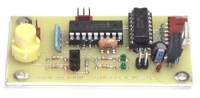
Initial Prototype
This is the initial prototype of the gizmo. While it was completely functional, it had a couple of problems:
- Enables on the 754410 were wired together and enabled "on" by default. This meant that powering up the board would activate all four relay outputs.
- The size was a bit larger than I would have liked, there was "wasted" board space.
P1
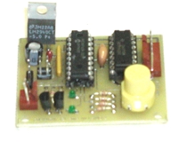
Second Prototype
This is the second prototype board. On this board great progress was made and the final size (1.75" x 2.00") was achieved. I went from four mounting holes to two as the other two were redundant when used with the Gizmo Bracket. However, as nice as it is, it too had a couple of problems:
- The servo connector is a 3 pin MOLEX header, this can be hard to find so I went with 4 pin headers on both the servo connector and the serial connector.
- As this was the generation where the true potential was recognized and I didn't want it to be just a weapons controller, I wanted to bring all six I/O pins out to the header on the right.
- At this stage it has SIG and CAL LEDs which are useful but now Power indicator. That was essential if the board is used in a bot as you need to know that it is on without testing it.
- There was a layout goof where I had one too few pins for the resistor pack. Easily fixed by cutting the resistor pack, but that needed fixing.
- The servo input could feed back voltage to the receiver if the servo input was pulled low. (not a lot but some) So I added a diode in series. This raises the minimum voltage level to 1.2V on the input but that's still under the 1.5V I've measured on Futaba receivers.
- Finally the layout needed some clean up to deal with the .250" overlap that the bracket would impose. That meant moving the 6-pin (now 8-pin) connector over and out of the way.
P2
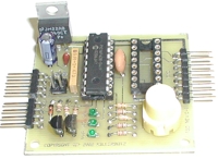
Third Prototype
At this point the design is pretty much complete and I'm shooting for manufacturability tweaks. This rev had one really bogus bug (short between 5v bus and V+ bus) which was caused by my cheap-ass ECAD tools that don't work on netlists. Its not easy to see in the picture but I now have 3 LEDs and have been experimenting with right angle pins for the board connects.
Other than that we had:
- Re-route PWR LED trace to give 12 mil spacing.
- Re-route RXD connector lead to give 12 mil spacing.
- Re-size button holes/pads for easier insertion and better annular ring.
- Re-spin power jumper to allow 5V to or from this board.
- Fix routing short between V+/5V busses.
A0
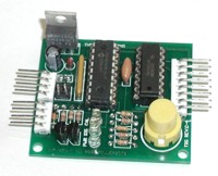
Initial Production Run
Now the hard work pays off. Here we have an image of the Gizmo complete with all the recommended components on its professionally produced printed circuit board. After checking and re-checking schematics and films I sent it off to a shop in Southern California to be made. ($175 NRE which I did not want to spend on re-spinning the board!)
The primary difference between the "pro" one and the prototype one is the soldermask and silkscreen, however the final version is also dimensionally accurate whereas the prototype ones from APC were rough cut to approximately the correct size.
The only "oops" on this board is that the legends "Servo" and "Serial" are covered by the 4 pin headers as are the legends for the 8 pin connector. This suggests that if I were to be aggressive I should either add legends to the bottom of the board or put them behind the connectors. This isn't/wasn't an issue with vertical connectors and really only comes into play with the right angle ones.
I also chose one green (PWR) and two amber LEDs (SIG, CAL) rather than 3 green or 1 green and 2 red. Further the LEDs are the flat top kind that are good for light pipes. This will work great in the bracket but they aren't as bright as the submini greens I used in the prototype.
Nominal weight 20 gms (just over half an ounce).