Various Circuits
Overview
This section describes various circuits that I use in many robots, typically they are for sensors or actuators.
Basic High Current "Sink"
 The high current driver circuit is used
when you need to supply more than a few mA to a load such as
an LED or a relay. In this example the I/O pin of your
microcontroller such as a BASIC Stamp is driving the base of
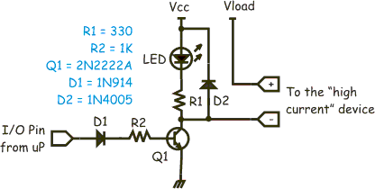
the transistor Q1 through a 1K resistor and diode D1. The diode is there
because if Vcc on the transistor is higher than 5V you don't want that
coming back into your microprocessor, the 1K resistor is there to limit the
current into the base of the transistor.
When using a CMOS output (such as a PIC) the output will go to about 5V, and subtracting the .7V the diode drops this will result in about 4.3mA flowing into the transistor. As this type of transistor has a typical gain (Hfe) of about 200 the transistor will fully saturate (turn on completely). Diode D2 acts as a "snub."
D2 is required when the "load" you are turning on has an inductor in it (such as a motor or a relay). When you turn "off" the transistor, the inductor in the relay/motor attempts to continue conducting current, since it cannot the voltage begins to rise (V = L*di/dt). If the voltage rises above that of the power supply then the power supply will begin "charging" (assuming a battery here, others just sink back current to ground, some fancy ones might turn off ). This prevents the transistor from having to deal with a very high voltage.
The LED in the example provides a visual indication that the circuit is "on" and your device should be responding. Typically R1 is 330 ohms or so to light up the LED. The resistor value is determined so that about 15mA of current will flow through the LED when the transistor is turned on, or the output (labeled "-") is grounded.
This circuit is called a "current sink" because current flowing out of "Vload" (power to your device) is being channeled (sunk) into the common ground. With the metal 2N2222 transistor this can handle a bit more than 1/2Amp continuous, probably 1 or 2 amps if they are short duration. Other transistors such as the NTE12 "high current" drivers can carry a bit more current.
Of course, if you just hook up the pad labeled "-" you will see that when the microprocessor pin is "1" that pin will be at zero volts, and when the microprocessor pin is at "0" the output pin will be at Vcc volts (limited to 15mA by the LED's resistor).
The down side of this circuit is that your device, what ever it is, sees a "ground" level that is actually about 200mV higher than the common ground. This is because the Collector-Emitter junction of the transistor is between your device and the real ground reference. What that means is that if you connect the minus side of the device accidentally to real ground then you'll get a current flowing. That may not be what you expect. If you must share a common ground, then your next best bet is the current "source." However, its a bit more complicated.
Basic High Current "Source"
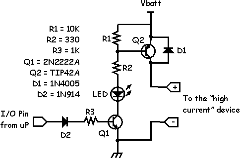
 The high current "source" is a
circuit that supplies current to the load. Unlike the current
"sink" circuit, the load and the system can share a
common ground. This is useful if you decide to make the
chassis of your robot "ground" for everything and
then you need only run a single power wire out to the high
current device.
This circuit is complicated by the fact that I designed it to work from a standard I/O pin that is not tolerant of voltages other than 5 volts and yet the "Vbatt" (your battery) voltage is very likely to be more than 5V. Things are further complicated by the fact that if the I/O pin is bi-directional you don't want it to "see" either a high input voltage or a lot of current. Thus the blocking diode to keep current flow going out of the pin.
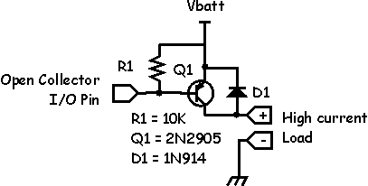
A simpler version of this circuit can be used if your I/O pins are "open collector" which means they are not internally tied to the Vcc pin of the microprocessor or I/O chip.
 In this circuit the I/O pin directly
connects to the base of Q1 (shown using a different
transistor). When the I/O pin is low, current flows out of
the base of the transistor to ground. Because the I/O pin can
only sink a few mA of current, you need to adjust your
transistor accordingly. Shown is a 2N2907 which is the
"sibling" of the 2n2222 but in PNP form rather than
NPN form. This circuit can source about 500mA continuously
and probably 1 to 1.5A for short bursts. You can source
higher currents if you use a darlington power transistor like
the TIP125. This will then source 3 to 5 amps!