Overview
As a number of people who have tried this know, there are never enough buttons and knobs to go around when you're doing a project. This lead me to design the "soft console." The term soft here describes its programmability, not its manufacture :-)

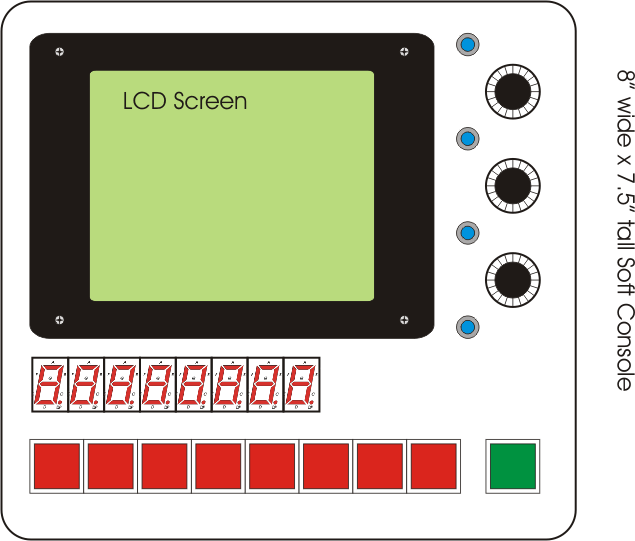
The image above shows the drawing I did to represent what it would look like. The I/O devices are as follows:
- LCD Screen - DM5001 Graphic LCD w/Character Generator and backlight. This screen is pretty cool, it has a "standard" 20 pin interface, can talk characters or graphics and uses and LED backlight. The down side is that it wants a -21V bias supply for the LCD.
- Four RGB LED Indicators - The four blue spots on the right are Nichia RGB LEDs mounted in a chrome LED panel mount. Each one is capable of displaying any color in the rainbow by simply modulating the R, G, and B LEDs that are in the package. This requires more pins than a simple LED would require but it is waaaay cooler.
- Three Quadrature Knobs - The three knobs to the right of the LCD are Quadrature encoder knobs. Each provides 2 bits of quadrature output to indicate they are being turned. See my article on quad encoders for more details of the ones I'm using.
- 8 7-segment LEDs - This was an area where I had to compromise a bit, in order to save I/O pins I chose to use an LED driver chip rather than my 8 digit display project. Now the advantage of compromising is that I get a nice bright display that is just as flexible but its using a dedicated chip to drive the LEDs.
- 9 Pushbutton Switches - Across the bottom of the console are a series of 9 pushbutton switches. These are illuminated NKK types sold by Digikey. They are all momentary but the right most one has a green LED and the left most 8 have red LEDs. The plan is that I can make them 'push on-push off' in the FPGA if I want to using the LED to indicate state, or momentary on, or whatever.
Not shown is the power switch. Out the "back" of this console come the BurchEd I/O ports (VGA, Mouse, Keyboard, Serial) and they are useful for hooking up more advanced peripherals. The result is the "FPGA Playground" where I can finish up the rest of my FPGA journey without worrying about spilling my Diet Dr. Pepper into the works of the machine.
The down side is that this console is just a bit to big for any of the "standard" enclosures so I'm stuck building something on my own with probably wood sides.
Current Progress -
As of this week (Dec 22nd, 2002) I'm working out the fabrication of the LCD bezel. I've started with a piece of 3/16" aluminum that I am milling out to the correct size on a Sherline Mill. In particular, to do this sort of work I'm starting out by drilling some holes in the center of the piece to provide anchor points. Next the four corner holes are drilled in their correct positions. Next the piece is secured via the anchor holes and the outer edge trimmed to size. Next to last a groove is cut in the aluminum that will provide a place for a piece of clear 1/16" thick polycarbonate (to protect the LCD). Once that is cut the inner hole is cut out and the outside edge becomes the mounting bracket.
--Chuck