Module: LCD Diagnostic Console
|
|
|
| Chuck McManis |
January 2003 |
|
|
|
Introduction
This project is a clever hack. It uses the basic ServoGizmo PCB and configures it to drive an Hitachi HD44780 based LCD device. If you read my "Pulse Measurement" project you can see I was using the LCD display on the LAB-X3 to display the width of pulses from the BASIC Stamp II. When I was debugging the high power speed controller software I used the Lab-X3 as a sort of console to interpret the codes that were flying between PIC1 and PIC2 on that project. It came in very handy for that so I thought I'd like to have something that was dedicated to doing just that.
Project Specifications
The Gizmo board brings out the pins of the PIC 16F628 that are connected to the internal UART. Since it is fairly easy to set up the PIC to read and write bytes serially using the UART this became the basis for this project. The first step was to build the hardware on which to run the diagnostic firmware.
The Gizmo normally drives a TI754410 H-bridge chip. However, if you leave off the H-bridge chip and simply bridge the pins on the printed circuit board you can route the PIC pins for RA0 thru RA3 straight out to the 8 pin connector. The pins RB4 and RB5 are already routed there by default so that gives you 6 pins to work with. Figure 1 shows the jumpers that are installed instead of the H-bridge chip. On the right side of the figure it shows the connection to the LCD from the Gizmo board.
Figure 1: Modification to get a 6 pin parallel I/O portThe red diagonal jumper connects the 5V Vcc line to the output. In this configuration the on-board voltage regulator is not used. Instead, the 5V line on the servo connector provides the system power. The other modification is a 1K resistor across the top which provides a 1K pull up for the RB4 line. I don't know if it is required, but it was on the Lab-X3 schematic so I've left it in. On my bench with a 4 line x 16 char display the system draws about 21 mA.
And that brings me to the next interesting bit, the Lab X3. One of the things I noticed with the Lab X3 is that the PIC talked to the LCD with only 6 pins rather than the 7 I would expect in a 4-bit interface. The "missing" pin is the R/W line which is tied to ground making the LCD a write-only device. When you think about it that's not such a bad optimization, after all you are the only one writing to it, and if you're a dedicated program you can keep the timing straight. As I had already written code to display data on the LCD with the 4Mhz PIC on the LAB-X3, I simply ported that code to work on the adapted Gizmo.
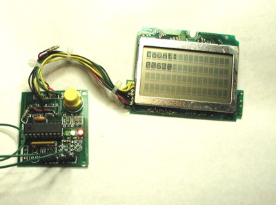
Photo 1: HLM3164 LCD attached to the modified Gizmo PCBAs you can see from the picture in Photo 1, the modification was entirely successful. I managed to hook up a older HLM3164 4 line x 16 character LCD to the board and display text on it. The only 'weird' thing is the resistor in the wiring, which is a 100 ohm resistor connected between Vee and ground. This was put there for the contrast adjustment. The "right" thing to do is to put a 5K potentiometer between Vcc and Gnd and to tie Vee to the wiper pin, however when I tried that I just left it at "max." Because it wasn't being useful I simply replaced the pot with a resistor connected to ground. This nearly duplicates the circuit used on the Lab-X3 although that system has a 2 line by 20 character display rather than a 4 line display.
A Note About LCDs
If you've read the LCD FAQ you know that there is sort of a 'standard' 14 pin connector at least for HD44780 based LCDs. The trick is finding out which pin is pin 1, from there its smooth sailing. If the connector is two rows of 7 pins then they are probably numbered horizontally then vertically (1,2 then 34, then 56, etc.) This project should work on pretty much any LCD with the HD44780 controller. As of this writing B&G Micro had one for $5 that was two lines by 20 characters.
Software Design
Eventually, the software will read data from the serial port and put it on the LCD panel, however for now I just needed something to test the LCD. That software, called LCDTEST, is described below. A zip file with the sources is available here.
There are four source files:
lcdtest.asm -- This is the main routine. It generates a count and displays it on the LCD.
16bits.inc -- This file includes a bunch of macros for manipulating 16 bit quantities on the PIC.
div16.asm -- This is a general purpose 16 x 16 divide routine for the PIC, I use it to convert to decimal in the LCDTEST program.
lcd.asm -- This is a collection of routines that initialize and talk to the LCD. They are '4Mhz' specific at the moment so if you use them and your system runs faster or slower than 4Mhz you will have to adapt them.
Future Direction
The software is designed to read characters from the serial port and put them on the display. I take advantage of the fact that ASCII is a 7 bit character field and treat anything with the high order bit set as a 'command'. Further, commands are grouped by the number of high order bits they have set (or conversely the location of the first zero bit.
B'11111111' - Clear the display of all characters.
B'11111110' - Reset the cursor to top left corner
B'11111101' - Display the text "ON"
B'11111100' - Display the text "OFF"
B'111110LL' - Turn on LED1 and LED2 (1 = on, 0 = off)
B'11110SRR' - Display next byte Signed (true/false) Radix (bin, dec, hex)
B'1110CCCC' - Display Text "RC = " where C will be one of 0 thru F
B'110DDDDD' -
B'10RCCCCC' - Position Cursor at Row R and column CCCC.
Availability
The software for this module can be downloaded as a HEX file, or for $5 I can mail you a pre-programmed PIC chip. (note that non-US addresses may require extra postage and handling)