Introduction
I've been programming PIC microprocessors from Microchip from the beginning. The openness of the PIC programming protocol has inspired literally dozens of people to build programmers for these devices. Further some, such as the one David Tait designed that was software driven and used a PC parallel port spawned a large number of follow on products. Some "open source" and some commercial products.
My first programmer was the PIC Start (not even the PIC Start Plus :-) which I got for "free" by attending a Microchip seminar on programming the PIC. Sure the seminar cost $99 which one could consider to be the price of the programmer, but training isn't free and the FAEs and TMEs that give these courses really understand the product. When I got serious I bought the Needham's EMP-20 (don't believe their line about "we'll just keep updating the software." because it is demonstrably not true. Where is the windows version ? Oh sorry you need to buy an entirely new programmer for that with all new system modules. No thanks!)
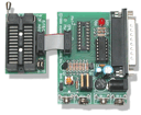
 My third
programmer was the EPIC32 from
MicroEngineering Labs.
This is shown in the image on the right. This is a very nice programmer and
it programs a lot of different PICs and it uses the parallel port just like
the EMP-20 does. (and the David Tait programmer for that matter). If you
read my "PIC Tools" article you know that I
also evaluated the Microchip ICD system. Granted, the ICD system is more
about teaching PIC programming than it is about programming PICs but it uses
the serial port which is nice, except laptops are losing serial ports and in
that article I said,
"Clearly the "next generation" programmers should be USB. This would allow them to work on either a MAC or a PC, have plug-n-play compatibility with a lot of PCs and laptops out there, and be fast as well.
Well guess what, the folks at www.kitsrus.com made a PIC programmer that can use USB. They called it their "Kit 149" (which later became 149a after 149b and 150 were released.) Not too surprisingly, Needham's upgraded their EMP-20 to the EMP-21 and added USB capability (and increased the price by 50%) but I'm not going there again, once was enough.
Getting the Kit
 As you
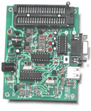
can imagine this is a "kit" which is short for "some assembly required." The
programmer (assembled) is shown on the right. You can click the image to get
a larger view. Fortunately the surface mount USB chip is already soldered to
the board.
I picked up my kit from Carl's Electronics for $29.95. This is significantly less expensive than the EPIC32 programmer ($59.95) however the "kit" isn't really complete. The kit does not come with a ZIF (Zero-insertion-force) socket, nor a "wall wart" power supply (you need an 18v supply). Also in later revs one of the crystals was changed to 6Mhz (from 4Mhz) so I needed an extra crystal. Fortunately everything I needed was available from JameCo electronics (they are about 15 miles from where I live). I added the following JameCo part numbers 163272 (18V wall wart), 101178 (coax jack known to fit said wall-wart), and 104029 (40 pin ZIF socket) to my kit. The parts from Jameco were about $20.75 so the total cost of the kit is more like $50.75.
Assembling the Kit
Of course once you get it you have to assemble it, and for many that is a high hurdle indeed. The assembly instructions were accurate but assumed you had assembled kits before. The instructions consist of "install the resistors, install the capacitors, install the rest, check the power and see if it works." (actually they are better than that, see the manual which is on-line.)
For me, assembly took about 4 hours with one 20 minute break. It was missing one component (a 47uF Electrolytic capacitor) which I replaced from my own parts stock. Some aspects of the manual differed from the kit I got (the rubber feet were already on the PCB) but for the most part it went together as you would expect. The use of 1/4 watt resistors and single line between pads design rules kept the board spacious enough that no special care was needed in soldering.
One of the nice touches is that the USB chip is not connected to the power bus initially. Once the kit is assembled, and before the chips are installed, you apply power and measure for 5V on a pair of convenient test points. Only after the test is passed do you solder in the jumper that will attach the 5v power rail to the USB chip. The helps prevent frying the USB chip with kit assembly errors.
Initial Testing and Bringup
The kit powered up and the first test is to try programming a chip with the serial port (the USB test comes later.) As there are updates to the firmware on the Kitsrus web site I thought why not make that my first test. I fired up the software supplied and installed a sacrificial 16F628-04/P. The good news was that the software correctly recognized the '628 after I plugged it in correctly, but this is a negative as well.
You see this programmer has a 40 pin ZIF socket, and the '628 is an 18 pin PIC. Do you plug the PIC in with pin1 to pin1 of the ZIF? No your don't! Instead the ZIF socket is wired so that different members of the PIC family plug into different places. So the software shows you a picture of where to plug in the chip you've selected. For the '628 this meant lining pin 1 of the PIC up with pin 2 of the ZIF socket. After moving the PIC, the software recognized it as expected.
I then tried programming the version 4 firmware into the PIC. This proceeded without error and I was quite pleased with myself until I tried to verify the program. Verify error at location 0x0000. The program had one value and the PIC was returning 0x0000. So I erased the PIC and tried again only to receive the same error. Frustrated, I got out the Microchip application note on PIC programming and read through the protocol. I used my oscilloscope to verify that the CLK and DAT signals were carrying data. It wasn't until I took the PIC over to my EPIC32 programmer to see if it could program it that the problem revealed itself.
As soon as I put the PIC into the EPIC32 programmer the software immediately reported that the PIC was code protected. Say what? As it turns out the firmware files on the Kitsrus site have the CP bit set in the option registers, and when you program a PIC with CP true the readback of that PIC is always, you guessed it, 0x0000. Argh! An hour and a half debugging nothing!
So I tried the USB programmer with some of my own PIC code and it worked fine. Yeah!
Bringing up the USB support was anti-climatic to say the least. I installed the USB driver from the FTDI web site And switched the programmer to USB mode. For some reason the USB com-port driver installed as COM7: but that worked with the software so I wasn't complaining. Then I tried it on my laptop (both running WinXP) and that worked too.
NOTE: This board uses an "A" USB connector to connect to the programmer. That means you need an USB A/A cable where both ends are "male." I happened to have one, but when I went to buy one they were no where to be found. The USB spec calls for devices to have the "B" connector so in that regard this unit violates the USB spec. If worst came to worst, you could splice two cable ends together.
Summary and Going Forward
The good news is that I now have a programmer that can program a wide variety of Microchip PIC devices that communicates with the host computer via USB. Assembly was straight forward and the inclusion of the schematic critical to my future plans. I learned about the FTDI chip and find that will probably be very useful to a number of hobbyists who are bemoaning the loss of general purpose I/O on PCs these days.
Going forward what I want is a PIC programmer that I can activate from the command line of a FreeBSD or Windows system. I asked about the protocol between the USB programmer and the PC and was politely rebuffed. The good news is that I too am a PIC program writer and I can read a data sheet as well as anyone can. Now I have a working programming circuit, I could even use the ICD to dynamically develop my programming software. Once that's done I'll post here on my website for others to use.
The Kitsrus folks added some useful things in their 149b version of this kit. Most notable is ICSP (In Circuit Serial Programming) capability. That is something I'd like but didn't get with the -a version (its a risk of being an early adopter).
The EPIC32 has the better ergonomics on the socket (you put pin 1 on pin 1) and Microengineering Labs has adapted the ICSP plug to connect to the socket, that's pretty handy too.
Bottom line is that the perfect programmer still doesn't exist, but this USB programmer is useful and a good choice for people using PIC chips.
--Chuck McManis
| Return to the Projects Page |