Speed Controller 2 - MORE CURRENT!
| By Chuck McManis | December 14, 2001 |
You cannot build a BattleBot without a speed controller, and unfortunately you cannot use my speed controller in a BattleBot (its too wimpy as it was designed for R/C type car motors, not serious motors.) So I've embarked on a project to build a bigger and badder speed controller that I can use in my BattleBot
Step One - Drive Some FETs
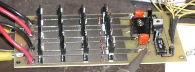
Step one is nearly complete, I've got a circuit that can drive 16 IRF1010E's ganged together in four groups of 4. You can see it below being driven by a BASIC Stamp II.
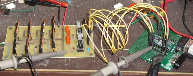
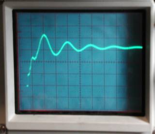
It seemed like a small step on the road to building the controller but then I realized I'm driving a 10Amp motor using a BASIC Stamp II. :-) The two scope probes are measuring the output of the BASIC Stamp II and the high side gate drive. A picture of what its seeing is here:
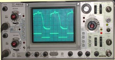
As you can see the high side has a weird "bounce" in the middle. I'm not sure what causes this. Also the turn off is nice and steep until about 3 uS and then it levels off. That wasn't expected, I thought it would be more gradual at the top and then fall off rapidly. So the bottom line is I still don't completely understand what this is doing but clearly we understand enough to make it work.
First Smoke
Of course to characterize this sort of things you have to figure out what is going to break when. Strangely enough on this design there is/was a 15V regulator acting as a voltage limiter on the charge reservoir. Clearly it gets yanked pretty hard when the high side capacitors charge but who would have figured it to go poof? It did in a spectacular release of magic blue smoke and with an impressive crack right down the front. I had suspected that the FETs, still running without heat sinks, might be the first to go but no. They were cooking along fine, slightly warm. Fortunately the switch losses in the driver circuitry has yet to show itself as a serious threat.
I put resistors on the gate capacitors to reduce ringing and it has worked wonderfully I think (very little ringing in the drivers) but that bump may or may not be related to the inductance of the gate driver path. On the next round of PC boards I've boosted the track width of the gate drive to reduce its inductance. That should be interesting.
![]()
October 12th, More Progress
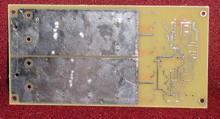
| The RevB board was finally done, this involved a lot of arguing with TraxMaker which did not want to create the kinds of fills that I wanted for the power traces. As you can see the top side of the board (shown above left) has 8 wide traces. Four of the traces are gate drive traces and four of them are two pair so Motor power, Motor Ground. | 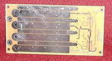 |
| The bottom side of the board (shown lower
right) has only two wide traces for the motor power. The gate drive
circuitry is to the right in the picture.
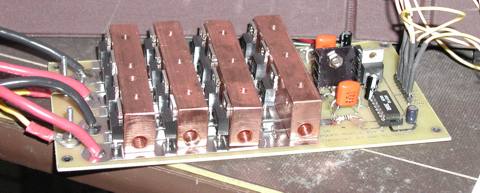
The stuffed board is then shown below, you can see the FETs all lined up in neat rows ready to carry current. When the copper heat bars are on them they will be covered with a heatsink.. |
 |
|
|
|
My thought was that the board could probably pass like this for a "simple" 50 or 60 amp controller. Especially if I use the lower Rds(on) type FETs. The down side of those FETs is their voltage range which would constrain the controller to being a "low voltage" controller.
I spent two days bringing up this stupid board. As it turned out a friend of mine found the fault which was a partially not-plated through hole on one of the sockets. Soldering from the top fixed it and we got to start running some characterization tests.
 The
nice thing was that drive circuitry is doing a good job of turning on all four
FETs. The waveform to the left is a very narrow view of the "on
transition." Basically the FETs are turning on in about 100 nS. They
actually are at full enhancement in about 70 nS and then there is a 3 uS
settling time. I've not figured out how to damp the ringing as I'm not sure of
its source.
The
nice thing was that drive circuitry is doing a good job of turning on all four
FETs. The waveform to the left is a very narrow view of the "on
transition." Basically the FETs are turning on in about 100 nS. They
actually are at full enhancement in about 70 nS and then there is a 3 uS
settling time. I've not figured out how to damp the ringing as I'm not sure of
its source.
Also of note the image on the left was taken with the bridge driving a purely resistive load. While driving a motor there are inductive feedback bounces that cause the scope to have difficulty holding the trigger. So far the ground bounce has stayed will within tolerance of the 5v that the driver circuits can deal with.
The gate drive was beefed up (see the heat sink on the board? :-) to be able to handle peaks of 6 - 8A of drive current. Between that and some stiffening capacitors the low side is rock solid and the high side rings just a tiny bit.
With luck my remote temperature probe will arrive tomorrow and then I can characterize the free-air performance of the FETs. For now I'm staying below 20Amps of drive current to keep the FETs in their safe operating region. The copper heat bars should be here on Tuesday so that will add another interesting step in the process.
As you might expect, heat dissipation is the primary concern on this bad boy. With 200 amps coursing through its electronic veins it should be pumping out about 240 watts of raw heat. Accepting that heat and whisking it away will be the job of a combination air/water cooling system.
![]()
Smoke 2, One FET down, 15 to go...
Well the next test was to run sustained at 10Amps in open air. Perhaps uniquely, first FET in the row of FETs is getting the hottest, it isn't clear if that is because its first in line, or because it was damaged during bring up (there was a time when it was shorted to ground for a while). To test that theory quickly and relatively easily, I'm trying to run the motor the other way for a while at 10Amps to see how that works ...
Nope two more FETs bite the dust. A single FET cannot carry 10 amps in free air, at least if they aren't in 'full enhencement' and these don't appear to be....
![]()
October 16th, two things arrive that make life cooler ...
Well this was a pretty good day from the mechanical side of things, I got both the radiator and the heat bars (custom made at NMPProducts). For those of you who have been having a hard time imagining what it was I was talking about, consider the picture below.
As you can see there are four copper bars that run transversely across the controller. The FETs screw down to these bars (very carefully :-). With mica insulators for isolation. Then the holes across the tops of the bars mount the L1 heat sink as shown below:
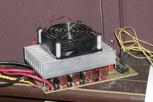 |
Now we're talking some cooling power! Actually the fin depth is limited a bit by our total space budget however it is actively cooled with a 24V fan. Depending on the fan I use we can get 2 to 10 ºC/Watt with this puppy. But do you see those holes in the copper bars? Well as soon as the fittings arrive we can hook this baby up to .. |
| THIS bad boy. Yes indeed, taking a cue from those crazy folks who like to water cool their PC's to get a 800 Mhz Celeron running at 2.4Ghz, I went out and purchased the HWLabs "Black Ice" radiator. Between the fan and the water system my calculations put us under the limit for running up to 1KW of dissipated power. With a room temperature reservoir I can get .5 ºC/Watt on this cooling system. Plenty of headroom for those awesome battles. | 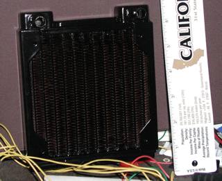 |
All in all it should be reasonably good at carrying current. On the other hand, given what some people claim are 160Amp speed controllers, I can't figure out why they don't have to dissipate as much heat (one has even fewer FETs than I do!) So perhaps that is a "peak current for less than 1 second" or something. Anyway, back to the circuit debugging...
Continuing the Saga (Nov-2001)
--Chuck