The Saga Continues (previous)

Of course BattleBots came and the speed controller was not quite ready, thus we went into battle with our Vantec RDFR38E. Big mistake, after whomping the other robot for 2 minutes and 15 seconds, Poof!, no more Vantec.
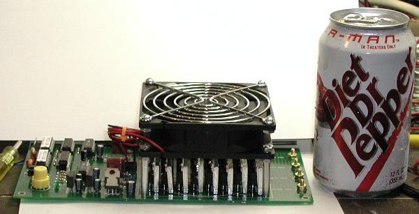
The power module is now pretty well characterized. The biggest issue was that I was not correctly driving the charge pump circuitry. This resulted in under pumped FETs, high resistance, and latch-up in one of my drivers. Once things latch up, the smoke begins. This argues for a fuse of some sort on the main line. But a 200Amp fuse is _huge_ and it wouldn't have helped anyway in this case.
Controlling the Demon
So I've turned my attention to the control aspects of things.
And as it turns out there is a lot to be learned here when you're throwing around a lot of juice. Perhaps the most important thing to achieve is not reversing direction "instantly." When I designed my first speed controller the PIC just does whatever you tell it. You say full forward in one pulse, you get full forward, and if you say full reverse in the next pulse you get full reverse. The physics however bite you in the ass.
If the controller is delivering full forward current, the motor has established a "back EMF" field that is exactly balancing the forward voltage, less work being done by the motor. Then you suddenly throw the thing into reverse.
Now the motor's windings are already fully charged to go the other direction, and the added voltage you're putting on the windings just makes things twice as good. Now you are getting double the voltage across the motor and a huge current spike. Yessiree Bob, the smoke can be released! So the trick then is to change direction in a controlled way.
| But what way would that be?
The graph on the right shows several choices in how you might want to
transition from 100% duty cycle PWM waveform going one direction to 100%
duty cycle PWM waveform going the other direction.
The three obvious choices are:
|
 Figure 1: Duty cycle vs Time graph |
Of course the graph I didn't draw was the "bad" one which looks like the edge of a square wave. 100% goes straight out 1/2 way, then drops immediately to -100% and continues on.
From the graph you can see that the exponential graph approaches the "bad" graph as the magnitude of the quadratic term goes up. Thus its primary benefit is that you cross zero rapidly but starting from 20%-30% rather than 100%. Clearly you can scale this to the FET voltages such that you'll get the fastest transition without blowing them up.
The linear transition is the easiest to implement (actually you can do all of them in look up tables but that's a design issue). This probably slows the transition from forward to reverse evenly and thus provides limited frequency response. (is this bad in a robot? I don't know)
Finally the quadratic version has the property of completely allowing the windings to get to 0 before you switch them. This should be the easiest on the motors/electronics but I've not tried it yet.
My software will allow me to select between any of these three "transitions" and the rate variable.
Interestingly, if you provide a sinusoidal transition pattern you've created a DC to AC inverter :-)
And still more...
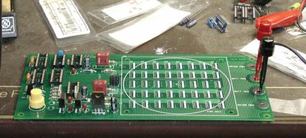
As you can see from above, the latest and greatest boards are now "official" in the sense that they are mean and green.
Unlike some speed controllers, I want mine to be "self contained" and that means that it takes a servo signal input and controls a motor. Nothing else to buy, so to speak. To that end there is some on-board intelligence. In this case a pair of PICs (PIC16F628) that are connected via their serial ports. (I like to call it a "two way SMP microkernel with serial cluster interconnect" as that sounds better than "a couple of PICs with their serial ports wired together" :-) The other advantage is that the PICs can drive the FETs in such a way that it is impossible to induce shoot through, or to ruin your day by slamming full speed motors from full forward to full reverse.
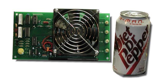
One PIC provides pulse measurement (reads the incoming servo pulse) and monitors the temperature of the FETs/Board. While the other PIC provides the PWM for the bridge and torque ramping. Of course how do you test this stuff without an in-circuit emulator? See below.

Yup, that is the LAB-X3 sitting there. My friend Ed Haas is a machinist and he often makes something that he then uses to make something else in his shop. I used that same technique here. I wrote two programs for the LAB-X3, one to pretend its PIC1 and one to pretend its PIC2. You can see it in the picture above pretending its PIC2.
In the picture the LAB-X3 is receiving "packets" on the serial port that are coming from PIC1 which is getting servo pulses from a Futaba receiver that is off the screen. The display shows that the last packet was VALID (its checksum was correct), the message was "REVERSE 5%" and the X3 had seen 63618 valid messages and 1 invalid message (when it powered up) Messages are things like forward, reverse, brake, and temperature. Each has a one byte "intensity" value so that "FORWARD 100%" means turn the bridge on full speed ahead, whereas "TEMPERATURE 150" means the FETs are about to melt down and to take appropriate action.
In PIC1 mode the quadrature knob is used to very the commands that are being sent from full forward to full reverse. With the buttons allowing one to send test temperature and brake commands.
You can see a packet "in flight" on the scope in the image below.
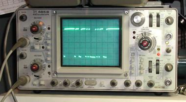
I've used an un used pin on PIC1 to trigger the scope when I start sending the packet that way it can catch it easily.
Is this cool or what?
Back to the Robotics Projects Page
--Chuck McManis